Friday 21 October 2011

Heart Rate Monitor


I was designing the heart-rate monitor wristband in CAD, and Yoakim was designing both the fish tank display and the fish, so that we could get them 3D printed. This was my process for designing the wristband.

Before I was able to model the wristband I needed to figure out what components where needed to go inside the model. Yoakim helped me figure out these components as he was focusing on the behaviour section. These components included 9 LED’s, the batteries, infrared sensor and the circuit board. Research into each component helped me determine the exact sizing of each component. After the components were modeled I had a clearer idea of thickness that the wristband needed to be in order to include the technology. 

I started with the following rough sketches playing with different designs.  
Experimenting with design and screen layout.
Experimenting with the battery connection.

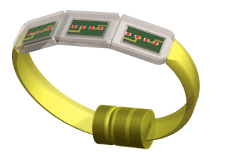
I wanted to keep the design as streamline as possible and I didn’t want it to represent something as similar as a watch design. Because of this I included the batteries in the join of the band rather than behind the face of the LED’s. This allowed for a thin (bracelet like) wristband, which was only powered when the two batteries were touching.

These are the CAD renders of the model I produced.

Yoakim was pleased with the design I produced however he wanted to alter the LED display screen:

Yoakim separated the screen I designed and made 3 individual screens instead. This was so that it would fit more comfortably on the users wrist. There are now 4 LED's within each screen. 
Exploded views displaying the inner components

Yoakim completed the CAD models for both the tank display and the fish. Here are the models combined in a render.
Yoakim forgot to include the lasers on the fish tank display model, so I added them in. You can clearly see here in this render how the two laser magnets are positioned on either side of the tank. This allows both sides to be moved simultaneously. 
This render shows the laser in action. It has been activated to communicate to the owner of the yellow fish, where the red fish (user) aims to be tomorrow.

SO Close.

Last week I developed an outline as to what I think needed to be included in the final presentation. I did this slide by slide for each section Scenario, Object and Behaviour. This is the initial outline I came up with for our presentation:

Scenario:

  • Persona - About
  • Persona - Problems
  • Research statement as proof of concept
  • Our specific criteria
  • Design brief statement 
  • Video
Object:
  • Hero image of tank display
  • In context with descriptive text
  • Hero of heart rate monitor
  • In context with text
  • Inner components of tank display
  • Inner components of heart rate monitor


Behaviour:
  • Exploded view
  • Infrared sensor detail
  • How the product works
  • Input and output diagram
  • Relevance of design statement
  • Product Specification

I was happy with the outline I came up with as it was a great help when it came to loading all of the necessary information into the layout.

I felt that our product needed to have a logo to brand it. So I did some rough sketches on what I thought would work well, and created the final logo design in Illustrator, playing with shape colour and font.

Wednesday 19 October 2011

3D Printing

After Yoakim modelled up the fish in CAD and he had it printed in the workshop, I went and collected them, ready for painting.
Yoakim's fish design.
Picking up the fish, SO exciting!

We originally intended for the fish to be printed on the new plastic 3D printer- this is why we left a small hole in the middle. We designed it so that there was room to insert a weight into the middle- in order to ensure the fish was heavy enough, so that it wouldn't move when not being controlled by the motor. As there was a confusion between us and the workshop our fish were printed on the sand printer. This wasn't a big issue - as this made the fish heavy enough, without the need for a weight inside. (Although the hole came in useful when I got to glueing the halves together..)

I wanted the fish to look semi-realistic. This, like most of the other tasks, took longer then expected. I had hoped..
The workshop men advised me on which glue was ideal for the powder based 3D printing. In order for it to work you had to mix the two tubes together. What a MESS that created..
The painted, glued together fish with string in the middles so that they can hang. I am happy with Yoakim's CAD designing and my craft skills..

Tuesday 18 October 2011

The last class for DNB601.

After the short briefing and re-capping of the presentation information, we were able to split into our groups and get into the work that still needed to be done before presentations the following week. We had our scenario script prepared for this class so we were able to head outside and do outdoor scenes to make the most of the provided time. I've included a couple behind the scene shots for your enjoyment.. 

The chips that were left behind.. (the final video will explain all)


Here is a blooper for some laughs.
Stay tuned for the final video !

After we had a couple of shots at each scene we came back to class to view our acting skills. The skills proved to be anything but amazing, but we had captured the scenes that we needed, success!